Using FreeRTOS in small embedded systems
Dieser Text stammt von Richard Barry, dem Autor von FreeRTOS. Man findet ihn online unter http://www.freertos.org/tutorial/.
Inhalt
1 Introduction
This section presents four contrasting design solutions to a hypothetical embedded real time application. The suitability of each solution is judged for embedded computers with varying RAM, ROM and processing capabilities. In addition the simplicity and corresponding maintainability of each design is assessed.
This is not intended to present an exhaustive list of possible designs, but a guide to the ways in which the FreeRTOS.orgtm real time kernel can be used.
NOTE: These pages have not yet been updated since the introduction of FreeRTOS V4.0.0. V4.0.0 introduces the concept of co-routines which would provide a different and novel solution to those presented here. The Tasks and Co-routines documentation provides further information.
2 The [hypothetical] Application
System context
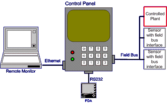
The application will execute on an embedded single board computer that must control a plant while maintaining both local and remote user interfaces.
Depicted above, the system consists of:
- An embedded computer within a control terminal.
- Two fieldbus networked sensors.
- The plant being controlled (could be anything, motor, heater, etc.). This is connected on the same fieldbus network.
- A matrix keypad that is scanned using general purpose IO.
- Two LED indicators.
- An LCD display.
- An embedded WEB server to which a remote monitoring computer can attach.
- An RS232 interface to a configuration utility that runs on a PDA.
3 Top Level Software Requirements
Here we are interested in the sequencing and timing requirements, rather than the exact functional requirements.
3.1 Plant Control
Each control cycle shall perform the following sequence:
- Transmit a frame on the fieldbus to request data from the networked sensors.
- Wait to receive data from both sensors.
- Execute the control algorithm.
- Transmit a command to the plant.
The control function of the embedded computer shall transmit a request every 10ms exactly, and the resultant command shall be transmitted within 5ms of this request. The control algorithm is reliant on accurate timing, it is therefore paramount that these timing requirements are met.
3.2 Local Operator Interface [keypad and LCD]
The keypad and LCD can be used by the operator to select, view and modify system data. The operator interface shall function while the plant is being controlled.
To ensure no key presses are missed the keypad shall be scanned at least every 15ms. The LCD shall update within 50ms of a key being pressed.
3.3 LED
The LED shall be used to indicate the system status. A flashing green LED shall indicate that the system is running as expected. A flashing red LED shall indicate a fault condition.
The correct LED shall flash on and off once ever second. This flash rate shall be maintained to within 50ms.
3.4 RS232 PDA Interface
The PDA RS232 interface shall be capable of viewing and accessing the same data as the local operator interface, and the same timing constraints apply - discounting any data transmission times.
3.5 TCP/IP Interface
The embedded WEB server shall service HTTP requests within one second.
4 Application components
The timing requirements of the hypothetical system can be split into three categories:
Strict timing - the plant control
The control function has a very strict timing requirement as it must execute every 10ms.
Flexible timing - the LED
While the LED outputs have both maximum and minimum time constraints, there is a large timing band within which they can function.
Deadline only timing - the human interfaces
This includes the keypad, LCD, RS232 and TCP/IP Ethernet communications.
The human interface functions have a different type of timing requirement as only a maximum limit is specified. For example, the keypad must be scanned at least every 10ms, but any rate up to 10ms is acceptable.
5 Solution #1: Why Use an RTOS Kernel?
5.1 Synopsis
Many applications can be produced without the use of an RTOS kernel and this page describes an approach that might be taken.
Even though the application in this case is probably too complex for such an approach the page is included to both highlight the potential problems and provide a contrast to the following RTOS based software designs.
5.2 Implementation
This solution uses a traditional infinite loop approach, whereby each component of the application is represented by a function that executes to completion.
Ideally a hardware timer would be used to schedule the time critical plant control function. However, having to wait for the arrival of data and the complex calculation performed make the control function unsuitable for execution within an interrupt service routine.
5.3 Concept of Operation
The frequency and order in which the components are called within the infinite loop can be modified to introduce some prioritisation. A couple of such sequencing alternatives are provided in the example below.
5.4 Evaluation
(+++) Small code size.
(+++) No reliance on third party source code.
(+++) No RTOS RAM, ROM or processing overhead.
(---) Difficult to cater for complex timing requirements.
(---) Does not scale well without a large increase in complexity.
- (---) Timing hard to evaluate or maintain due to the interdependencies
- between the different functions.
5.5 Conclusion
The simple loop approach is very good for small applications and applications with flexible timing requirements - but can become complex, difficult to analyse and difficult to maintain if scaled to larger systems.
5.6 Example
This example is a partial implementation of the hypothetical application introduced previously
The Plant Control Function
The control function can be represented by the following pseudo code:
void PlantControlCycle( void ) {
    TransmitRequest();
    WaitForFirstSensorResponse();

    if( Got data from first sensor )
    {
        WaitForSecondSensorResponse();

        if( Got data from second sensor )
        {
            PerformControlAlgorithm();
            TransmitResults();
        }
    }
}
5.7 The Human Interface Functions
This includes the keypad, LCD, RS232 communications and embedded WEB server.
The following pseudo code represents a simple infinite loop structure for controlling these interfaces.
int main( void )
{
    Initialise();

    for( ;; )
    {
        ScanKeypad();
        UpdateLCD();
        ProcessRS232Characters();
        ProcessHTTPRequests();
    }

    // Should never get here.
    return 0;
}
This assumes two things: First, The communications IO is buffered by interrupt service routines so peripherals do not require polling. Second, the individual function calls within the loop execute quickly enough for all the maximum timing requirements to be met.
5.8 Scheduling the Plant Control Function
The length of the control function means it cannot simply be called from a 10ms timer interrupt.
Adding it to the infinite loop would require the introduction of some temporal control. For example ... :
// Flag used to mark the time at which a
// control cycle should start (mutual exclusion
// issues being ignored for this example).
int TimerExpired;

// Service routine for a timer interrupt.  This
// is configured to execute every 10ms.
void TimerInterrupt( void )
{
    TimerExpired = true;
}


// Main() still contains the infinite loop -
// within which a call to the plant control
// function has been added.
int main( void )
{
    Initialise();

    for( ;; )
    {
        // Spin until it is time for the next
        // cycle.
        if( TimerExpired )
        {
            PlantControlCycle();
            TimerExpired = false;

            ScanKeypad();
            UpdateLCD();

            // The LEDs could use a count of
            // the number of interrupts, or a
            // different timer.
            ProcessLEDs();

            // Comms buffers must be large
            // enough to hold 10ms worth of
            // data.
            ProcessRS232Characters();
            ProcessHTTPRequests();
        }

        // The processor can be put to sleep
        // here provided it is woken by any
        // interrupt.
    }

    // Should never get here.
    return 0;
}
... but this is not an acceptable solution:
- A delay or fault on the field bus results in an increased execution time of the plant control function. The timing requirements of the interface functions would most likely be breached.
- Executing all the functions each cycle could also result in a breach of the control cycle timing.
- Jitter in the execution time may cause cycles to be missed. For example the execution time of ProcessHTTPRequests() could be negligible when no HTTP requests have been received, but quite lengthy when a page was being served.
- It is not very maintainable - it relies on every function being executed within the maximum time.
- The communication buffers are only serviced once per cycle necessitating their length to be larger than would otherwise be necessary.
5.9 Alternative Structures
Two factors can be identified that limit the suitability of the simple loop structure described so far.
The length of each function call
Allowing each function to execute in its entirety takes too long. This can be prevented by splitting each function into a number of states. Only one state is executed each call. Using the control function as an example:
// Define the states for the control cycle function.
typdef enum eCONTROL_STATES
{
    eStart, // Start new cycle.
    eWait1, // Wait for the first sensor response.
    eWait2  // Wait for the second sensor response.
} eControlStates;

void PlantControlCycle( void )
{
static eControlState eState = eStart;

    switch( eState )
    {
        case eStart :
            TransmitRequest();
            eState = eWait1;
            break;

        case eWait1;
            if( Got data from first sensor )
            {
                eState = eWait2;
            }
            // How are time outs to be handled?
            break;

        case eWait2;
            if( Got data from first sensor )
            {
                PerformControlAlgorithm();
                TransmitResults();

                eState = eStart;
            }
            // How are time outs to be handled?
            break;
    }
}
This function is now structurally more complex, and introduces further scheduling problems. The code itself will become harder to understand as extra states are added - for example to handle timeout and error conditions.
The granularity of the timer
A shorter timer interval will give more flexibility.
Implementing the control function as a state machine (an in so doing making each call shorter) may allow it to be called from a timer interrupt. The timer interval will have to be short enough to ensure the function gets called at a frequency that meets its timing requirements. This option is fraught with timing and maintenance problems.
Alternatively the infinite loop solution could be modified to call different functions on each loop - with the high priority control function called more frequently:
int main( void )
{
int Counter = -1;

    Initialise();

    // Each function is implemented as a state
    // machine so is guaranteed to execute
    // quickly - but must be called often.

    // Note the timer frequency has been raised.

    for( ;; )
    {
        if( TimerExpired )
        {
            Counter++;

            switch( Counter )
            {
                case 0  : ControlCycle();
                          ScanKeypad();
                          break;

                case 1  : UpdateLCD();
                          break;

                case 2  : ControlCycle();
                          ProcessRS232Characters();
                          break;

                case 3  : ProcessHTTPRequests();

                          // Go back to start
                          Counter = -1;
                          break;

            }

            TimerExpired = false;
        }
    }
    // Should never get here.
    return 0;
}
More intelligence can be introduced by means of event counters, whereby the lower priority functionality is only called if an event has occurred that requires servicing:
for( ;; )
    {
        if( TimerExpired )
        {
            Counter++;

            // Process the control cycle every other loop.
            switch( Counter )
            {
                case 0  : ControlCycle();
                          break;

                case 1  : Counter = -1;
                          break;
            }

            // Process just one of the other functions.  Only process
            // a function if there is something to do.  EventStatus()
            // checks for events since the last iteration.
            switch( EventStatus() )
            {
                case EVENT_KEY  :   ScanKeypad();
                                    UpdateLCD();
                                    break;

                case EVENT_232  :   ProcessRS232Characters();
                                    break;

                case EVENT_TCP  :   ProcessHTTPRequests();
                                    break;
            }

            TimerExpired = false;
        }
    }
Processing events in this manner will reduce wasted CPU cycles but the design will still exhibit jitter in the frequency at which the control cycle executes.
6 Solution #2: A Fully Preemptive System
6.1 Synopsis
This is a traditional preemptive multitasking solution. It makes full use of the RTOS services with no regard to the resultant memory and processor overhead. There is a simplistic partitioning of the required functionality to a number of autonomous tasks.
6.2 Implementation
A separate task is created for each part of the system that can be identified as being able to exist in isolation, or as having a particular timing requirement.
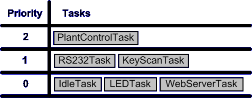
Solution #2 functions tasks and priorities
Tasks will block until an event indicates that processing is required. Events can either be external (such as a key being pressed), or internal (such as a timer expiring).
Priorities are allocated to tasks in accordance to their timing requirements. The stricter the timing requirement the higher the priority.
6.3 Concept of Operation
The highest priority task that is able to execute (is not blocked) is the task guaranteed by the RTOS to get processor time. The kernel will immediately suspend an executing task should a higher priority task become available.
This scheduling occurs automatically, with no explicit knowledge, structuring or commands within the application source code. It is however the responsibility of the application designers to ensure that tasks are allocated an appropriate priority.
When no task is able to execute the idle task will execute. The idle task has the option of placing the processor into power save mode.
6.4 Scheduler Configuration
The scheduler is configured for preemptive operation. The kernel tick frequency should be set at the slowest value that provides the required time granularity.
6.5 Evaluation
(+++) Simple, segmented, flexible, maintainable design with few interdependencies.
(+++) Processor utilisation is automatically switched from task to task on a most urgent need basis with no explicit action required within the application source code.
(+) Power consumption can be reduced if the idle task places the processor into power save (sleep) mode, but may also be wasted as the tick interrupt will sometimes wake the processor unnecessarily.
(+) The kernel functionality will use processing resources. The extent of this will depend on the chosen kernel tick frequency.
(---) This solution requires a lot of tasks, each of which require their own stack, and many of which require a queue on which events can be received. This solution therefore uses a lot of RAM.
(---) Frequent context switching between tasks of the same priority will waste processor cycles.
6.6 Conclusion
This can be a good solution provided the RAM and processing capacity is available. The partitioning of the application into tasks and the priority assigned to each task requires careful consideration.
6.7 Example
This example is a partial implementation of the hypothetical application introduced previously. The FreeRTOS.org API is used.
6.8 Plant Control Task
This task implements all the control functionality. It has critical timing requirements and is therefore given the highest priority within the system:
#define CYCLE_RATE_MS       10
#define MAX_COMMS_DELAY     2

void PlantControlTask( void *pvParameters )
{
portTickType xLastWakeTime;
DataType Data1, Data2;

    InitialiseTheQueue();

    // A
    xLastWakeTime = xTaskGetTickCount();

    // B
    for( ;; )
    {
        // C
        vTaskDelayUntil( &xLastWakeTime, CYCLE_RATE_MS );

        // Request data from the sensors.
        TransmitRequest();

        // D
        if( xQueueReceive( xFieldBusQueue, &Data1, MAX_COMMS_DELAY ) )
        {
            // E
            if( xQueueReceive( xFieldBusQueue, &Data2, MAX_COMMS_DELAY ) )
            {
                PerformControlAlgorithm();
                TransmitResults();
            }
        }
    }
    // Will never get here!
}
Referring to the labels within the code fragment above:
- xLastWakeTime is initialised. This variable is used with the vTaskDelayUntil() API function to control the frequency at which the control function executes.
- This function executes as an autonomous task so must never exit.
- vTaskDelayUntil() tells the kernel that this task should start executing exactly 10ms after the time stored in xLastWakeTime. Until this time is reached the control task will block. As this is the highest priority task within the system it is guaranteed to start executing again at exactly the correct time. It will pre-empt any lower priority task that happens to be running.
- There is a finite time between data being requested from the networked sensors and that data being received. Data arriving on the field bus is placed in the xFieldBusQueue by an interrupt service routine, the control task can therefore make a blocking call on the queue to wait for data to be available. As before, because it is the highest priority task in the system it is guaranteed to continue executing immediately data is available.
- As 'D', waiting for data from the second sensor.
A return value of 0 from xQueueReceive() indicates that no data arrived within the specified block period. This is an error condition the task must handle. This and other error handling functionality has been omitted for simplicity.
6.9 Embedded WEB Server Task
The embedded WEB server task can be represented by the following pseudo code. This only utilises processor time when data is available but will take a variable and relatively long time to complete. It is therefore given a low priority to prevent it adversely effecting the timing of the plant control, RS232 or keypad scanning tasks.
void WebServerTask( void *pvParameters )
{
DataTypeA Data;

    for( ;; )
    {
        // Block until data arrives.  xEthernetQueue is filled by the
        // Ethernet interrupt service routine.
        if( xQueueReceive( xEthernetQueue, &Data, MAX_DELAY ) )
        {
            ProcessHTTPData( Data );
        }
    }
}
6.10 RS232 Interface
This is very similar in structure to the embedded WEB server task. It is given a medium priority to ensure it does not adversely effect the timing of the plant control task.
void RS232Task( void *pvParameters )
{
DataTypeB Data;

    for( ;; )
    {
        // Block until data arrives.  xRS232Queue is filled by the
        // RS232 interrupt service routine.
        if( xQueueReceive( xRS232Queue, &Data, MAX_DELAY ) )
        {
            ProcessSerialCharacters( Data );
        }
    }
}
6.11 Keypad Scanning Task
This is a simple cyclical task. It is given a medium priority as it's timing requirements are similar to the RS232 task.
The cycle time is set much faster than the specified limit. This is to account for the fact that it may not get processor time immediately upon request - and once executing may get pre-empted by the plant control task.
#define DELAY_PERIOD 4

void KeyScanTask( void *pvParmeters )
{
char Key;
portTickType xLastWakeTime;

    xLastWakeTime = xTaskGetTickCount();

    for( ;; )
    {
        // Wait for the next cycle.
        vTaskDelayUntil( &xLastWakeTime, DELAY_PERIOD );

        // Scan the keyboard.
        if( KeyPressed( &Key ) )
        {
            UpdateDisplay( Key );
        }
    }
}
If the overall system timing were such that this could be made the lowest priority task then the call to vTaskDelayUntil() could be removed altogether. The key scan function would then execute continuously whenever all the higher priority tasks were blocked - effectively taking the place of the idle task.
6.12 LED Task
This is the simplest of all the tasks.
#define DELAY_PERIOD 1000

void LEDTask( void *pvParmeters )
{
portTickType xLastWakeTime;

    xLastWakeTime = xTaskGetTickCount();

    for( ;; )
    {
        // Wait for the next cycle.
        vTaskDelayUntil( &xLastWakeTime, DELAY_PERIOD );

        // Flash the appropriate LED.
        if( SystemIsHealthy() )
        {
            FlashLED( GREEN );
        }
        else
        {
            FlashLED( RED );
        }
    }
}
7 Solution #3: Reducing RAM Utilisation
NOTE: These pages have not yet been updated since the introduction of FreeRTOS V4.0.0. V4.0.0 introduces the concept of co-routines which would provide a different and novel solution to those presented here. The Tasks and Co-routines documentation provides further information.
7.1 Synopsis
Solution #2 makes full use of the RTOS. This results in a clean design, but one that can only be used on embedded computers with ample RAM and processing resource. Solution #3 attempts to reduce the RAM usage by changing the partitioning of functionality into tasks.
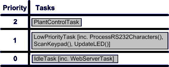
Solution #3 functions tasks and priorities
We have previously seen how the timing requirements of our hypothetical application can be split into three categories:
Strict timing - the plant control
As before, a high priority task is created to service the critical control functionality.
Deadline only timing - the human interfaces
Solution #3 groups the RS232, keyscan and LED functionality into a single medium priority task.
For reasons previously stated it is desirable for the embedded WEB server task to operate at a lower priority. Rather than creating a task specifically for the WEB server an idle task hook is implemented to add the WEB server functionality to the idle task. The WEB server must be written to ensure it never blocks!
Flexible timing - the LED
The LED functionality is too simple to warrant it's own task if RAM is at a premium. For reasons of demonstration this example includes the LED functionality in the single medium priority task. It could of coarse be implemented in a number of ways (from a peripheral timer for example).
Tasks other than the idle task will block until an event indicates that processing is required. Events can either be external (such as a key being pressed), or internal (such as a timer expiring).
Concept of Operation
The grouping of functionality into the medium priority task has three important advantages over the infinite loop implementation presented in solution #1:
- The use of a queue allows the medium priority task to block until an event causes data to be available - and then immediately jump to the relevant function to handle the event. This prevents wasted processor cycles - in contrast to the infinite loop implementation whereby an event will only be processed once the loop cycles to the appropriate handler.
- The use of the real time kernel removes the requirement to explicitly consider the scheduling of the time critical task within the application source code.
- The removal of the embedded WEB server function from the loop has made the execution time more predictable.
In addition, the functionality that has been grouped into a single task is taken from several tasks that previously shared the same priority anyway (barr the LED function). The frequency at which code at this priority executes will not alter whether in a single or multiple tasks.
The plant control task, as the highest priority task, is guaranteed to be allocated processing time whenever it requires. It will pre-empt the low and medium priority tasks if necessary. The idle task will execute whenever both application tasks are blocked. The idle task has the option of placing the processor into power save mode.
Evaluation
(+++) Creates only two application tasks so therefore uses much less RAM than solution #2.
(+++) Processor utilisation is automatically switched from task to task on a most urgent need basis.
(+++) Utilising the idle task effectively creates three application task priorities with the overhead of only two.
(+) The design is still simple but the execution time of the functions within the medium priority task could introduce timing issues. The separation of the embedded WEB server task reduces this risk and in any case any such issues would not effect the plant control task.
(+) Power consumption can be reduced if the idle task places the CPU into power save (sleep) mode, but may also be wasted as the tick interrupt will sometimes wake the CPU unnecessarily.
(+) The RTOS functionality will use processing resources. The extent of this will depend on the chosen kernel tick frequency.
(---) The design might not scale if the application grows too large.
7.2 Conclusion
This can be a good solution for systems with limited RAM but it is still processor intensive. Spare capacity within the system should be checked to allow for future expansion.
7.3 Example
This example is a partial implementation of the hypothetical application introduced previously. The FreeRTOS.org API is used.
7.4 Plant Control Task
The plant control task is identical to that described in solution #2.
7.5 The Embedded WEB Server
This is simply a function that is called from the idle task and runs to completion.
7.6 The medium Priority Task
The medium priority task can be represented by the following pseudo code.
#define DELAY_PERIOD 4
#define FLASH_RATE 1000

void MediumPriorityTask( void *pvParameters )
{
xQueueItem Data;
portTickType FlashTime;

    InitialiseQueue();
    FlashTime = xTaskGetTickCount();

    for( ;; )
    {
        do
        {
            // A
            if( xQueueReceive( xCommsQueue, &Data, DELAY_PERIOD ) )
            {
                ProcessRS232Characters( Data.Value );
            }

          // B
        } while ( uxQueueMessagesWaiting( xCommsQueue ) );

        // C
        if( ScanKeypad() )
        {
            UpdateLCD();
        }

        // D
        if( ( xTaskGetTickCount() - FlashTime ) >= FLASH_RATE )
        {
            FlashTime = xTaskGetTickCount();
            UpdateLED();
        }
    }

    // Should never get here.
    return 0;
}
Referring to the labels within the code fragment above:
- The task first blocks waiting for a communications event. The block time is relatively short.
- The do-while loop executes until no data remains in the queue. This implementation would have to be modified if data arrives too quickly for the queue to ever be completely empty.
- Either the queue has been emptied of all data, or no data arrived within the specified blocking period. The maximum time that can be spent blocked waiting for data is short enough to ensure the keypad is scanned frequently enough to meet the specified timing constraints.
- Check to see if it is time to flash the LED. There will be some jitter in the frequency at which this line executes, but the LED timing requirements are flexible enough to be met by this implementation.
8 Solution #4: Reducing the Processor Overhead
NOTE: These pages have not yet been updated since the introduction of FreeRTOS V4.0.0. V4.0.0 introduces the concept of co-routines which would provide a different and novel solution to those presented here. The Tasks and Co-routines documentation provides further information.
8.1 Synopsis
Solution #2 showed how a clean application can be produced by fully utilising the RTOS functionality. Solution #3 showed how this can be adapted for embedded computers with limited RAM resource. Solution #4 makes further modifications with the objective of a reduction in the RTOS processing overhead.
A hybrid scheduling algorithm (neither fully preemptive or fully cooperative) is created by configuring the kernel for cooperative scheduling, then performing context switching from within event interrupt service routines.
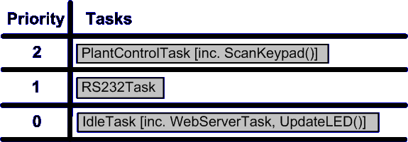
Solution #4 functions tasks and priorities
The critical plant control functionality is once again implemented by a high priority task but the use of the cooperative scheduler necessitates a change to its implementation. Previously the timing was maintained using the vTaskDelayUntil() API function. When the preemptive scheduler was used, assigning the control task the highest priority ensured it started executing at exactly the specified time. Now the cooperative scheduler is being used - therefore a task switch will only occur when explicitly requested from the application source code so the guaranteed timing is lost.
Solution #4 uses an interrupt from a peripheral timer to ensure a context switch is requested at the exact frequency required by the control task. The scheduler ensures that each requested context switch results in a switch to the highest priority task that is able to run.
The keypad scanning function also requires regular processor time so it too is executed within the task triggered by the timer interrupt. The timing of this task can be easily evaluated; The worst case processing time of the control function is given by the error case - when no data is forthcoming from the networked sensors causing the control function to time out. The execution time of the keypad scanning function is basically fixed. We can therefore be certain that chaining their functionality in this manner will never result in jitter in the control cycle frequency - or worse still a missed control cycle.
The RS232 task will be scheduled by the RS232 interrupt service routine.
The flexible timing requirements of the LED functionality means it can probably join the embedded WEB server task within the idle task hook. If this is not adequate then it too can be moved up to the high priority task.
8.2 Concept of Operation
The cooperative scheduler will only perform a context switch when one is explicitly requested. This greatly reduces the processor overhead imposed by the RTOS. The idle task, including the embedded WEB server functionality, will execute without any unnecessary interruptions from the kernel.
An interrupt originating from either the RS232 or timer peripheral will result in a context switch exactly and only when one is necessary. This way the RS232 task will still pre-empt the idle task, and can still itself be pre-empted by the plant control task - maintaining the prioritised system functionality.
8.3 Scheduler Configuration
The scheduler is configured for cooperative operation. The kernel tick is used to maintain the real time tick value only.
Evaluation
(+++) Creates only two application tasks so therefore uses much less RAM than solution #2.
(+++) The RTOS processing overhead is reduced to a minimum.
(+) Only a subset of the RTOS features are used. This necessitates a greater consideration of the timing and execution environment at the application source code level, but still allows for a greatly simplified design (when compared to solution #1).
(---) Reliance on processor peripherals. Non portable.
(---) The problems of analysis and interdependencies between modules as were identified with solution #1 are starting to become a consideration again - although to a much lesser extent.
(---) The design might not scale if the application grows too large
8.4 Conclusion
Features of the RTOS kernel can be used with very little overhead, enabling a simplified design even on systems where processor and memory constraints prevent a fully preemptive solution.
8.5 Example
This example is a partial implementation of the hypothetical application introduced previously. The FreeRTOS.org API is used.
8.6 High Priority Task
The high priority task is triggered by a semaphore 'given' by a periodic interrupt service routine:
void vTimerInterrupt( void )
{
    // 'Give' the semaphore.  This will wake the high priority task.
    xSemaphoreGiveFromISR( xTimingSemaphore );

    // The high priority task will now be able to execute but as
    // the cooperative scheduler is being used it will not start
    // to execute until we explicitly cause a context switch.
    taskYIELD();
}
Note that the syntax used to force a context switch from within an ISR is different for different ports. Do not copy this example directly but instead check the documentation for the port you are using.
The high priority task contains both the plant control and keypad functionality. PlantControlCycle() is called first to ensure consistency in its timing.
void HighPriorityTaskTask( void *pvParameters )
{
    // Start by obtaining the semaphore.
    xSemaphoreTake( xSemaphore, DONT_BLOCK );

    for( ;; )
    {
        // Another call to take the semaphore will now fail until
        // the timer interrupt has called xSemaphoreGiveFromISR().
        // We use a very long block time as the timing is controlled
        // by the frequency of the timer.
        if( xSemaphoreTake( xSemaphore, VERY_LONG_TIME ) == pdTRUE )
        {
            // We unblocked because the semaphore became available.
            // It must be time to execute the control algorithm.
            PlantControlCycle();

            // Followed by the keyscan.
            if( KeyPressed( &Key ) )
            {
                UpdateDisplay( Key );
            }
        }

        // Now we go back and block again until the next timer interrupt.
    }
}
8.7 RS232 Task
The RS232 task simply blocks on a queue waiting for data to arrive. The RS232 interrupt service routine must post the data onto the queue - making the task ready to run - then force a context switch. This mechanism is as per the timer interrupt pseudo code given above.
The RS232 task can therefore be represented by the following pseudo code:
void vRS232Task( void *pvParameters )
{
DataType Data;

    for( ;; )
    {
       if( cQueueReceive( xRS232Queue, &Data, MAX_DELAY ) )
        {
            ProcessRS232Data( Data );
        }
    }
}
8.8 The Embedded WEB Server and LED Functionality
The remaining system functionality is placed within the idle task hook. This is simply a function that is called by each cycle of the idle task.
void IdleTaskHook( void )
{
static portTickType LastFlashTime = 0;

    ProcessHTTPRequests();

    // Check the tick count value to see if it is time to flash the LED
    // again.
    if( ( xTaskGetTickCount() - LastFlashTime ) > FLASH_RATE )
    {
        UpdateLED();

        // Remember the time now so we know when the next flash is due.
        LastFlashTime = xTaskGetTickCount();
    }
}