|

Areas: HW products - Web51 - x51 Library Sections: Docs - Construction - Cool Ideas - Software - Programming - Beginners Editorial sections Contacts - Sitemap - News - Links |
|
RS 485 & RS 422Great introduction to the industry standard for point-to-point and multipoint serial communication.Preface:Are you an electronics amateur, or a future professional, designing an electronics application? If it consists of several units in different places, you probably need a way for them to communicate with each other. Maybe you are interested in data transfer related topics of microprocessor and computer applications? Or, are you interested in RS 232, RS 422 and RS 485, transfer protocols, and related areas? Then, this article is right for you. Thanks to: No Guarantee: Chapter 1: What is RS 422, RS 485, comparison with RS 232RS 232 is well-known due to popularity of today's PC's, unlike the RS422 and RS 485. These are used in industry for control systems and data transfers (small volumes, NO hundreds of Mb/s). So, what is the main difference between RS 232 and RS 422 & 485? The RS 232 signals are represented by voltage levels with respect to ground. There is a wire for each signal, together with the ground signal (reference for voltage levels). This interface is useful for point-to-point communication at slow speeds. For example, port COM1 in a PC can be used for a mouse, port COM2 for a modem, etc. This is an example of point-to-point communication: one port, one device. Due to the way the signals are connected, a common ground is required. This implies limited cable length - about 30 to 60 meters maximum. (Main problems are interference and resistance of the cable.) Shortly, RS 232 was designed for communication of local devices, and supports one transmitter and one receiver. RS 422 & 485 uses a different principle: Each signal uses one twistedpair (TP) line - two wires twisted around themselves. We're talking 'Balanced data transmission', or 'Differential voltage transmission'. Simply, let's label one of the TP wires 'A' and the other one 'B'. Then, the signal is inactive when the voltage at A is negative and the voltage at B is positive. Otherwise, the signal is active, A is positive and B is negative. Of course, the difference between the wires A and B matters. For RS 422 & 485 the cable can be up to 1200 meters (4000 feet) long, and commonly available circuits work at 2.5 MB/s transfer rate. What is the difference between RS 422 and RS 485? Electrical principle is the same: both use differential transmitters with alternating voltages 0 and 5V. However, RS 422 is intended for point-to-point communications, like RS 232. RS 422 uses two separate TP wires, data can be transferred in both directions simultaneously. RS 422 is often used to extend a RS 232 line, or in industrial environments. RS 485 is used for multipoint communications: more devices may be connected to a single signal cable - similar to e.g. ETHERNET networks, which use coaxial cable. Most RS 485 systems use Master/Slave architecture, where each slave unit has its unique address and responds only to packets addressed to this unit. These packets are generated by Master (e.g. PC), which periodically polls all connected slave units. This article will mainly cover the Master/Slave architecture because it is sufficient for 95% of applications. In special cases (security systems, ...), an improved version of multiprocessor communication is used. This system uses only a single line for bidirectional communication; however, there is no Master. All units announce a packet transmission of a specified length, and at the same time listen whether the data has been successfully transmitted. If it's not the case, they stop communicating and listen for what has happened. At this time, urgent packets can be transmitted over the line. This system is ideal for devices, that need to immediately transfer some very important and up-to-date data, without waiting for Master to give them a chance to do so. On the other side, useful data transfer is less effective (about 30% less effective than the first system).
RS 485 exists in two versions: 1 TwistedPair or 2 TwistedPairs
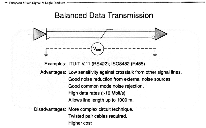
In this version, all devices are connected to a single TwistedPair. Thus, all of them must have drivers with tri-state outputs (including the Master). Communication goes over the single line in both directions. It is important to prevent more devices from transmitting at once (software problem). Here, Master does not have to have tri-state output, since Slave devices transmit over the second twistedpair, which is intended for sending data from Slave to Master. This solution often allows to implement multipoint communication in systems, which were originally designed (HW as well as SW) for RS232. Of course, Master software needs to be modified, so that Master periodically sends query packets to all Slave devices. Increased data throughput is evident in large volumes. Sometimes you can see a RS 485 system in a point-to-point system. It is virtually identical to RS 422; the high impedance state of the RS 485 output driver is not used. The only difference in hardware of the RS 485 and RS 422 circuits is the ability to set the output to high impedance state. Chapter 2: Balanced differential signalsFirst, let's talk about advantages and disadvanteges of RS 422/485. For a basic RS 422/485 system, we need an I/O driver with differential outputs and an I/O receiver with differential inputs. Noise and interference is introduced into the line; however, since the signal is transferred via a twisted pair of wires, the voltage difference (between A and B) of this interference is almost zero. Due to the differential function of the RS 422/485 input amplifier of the receiver, this interference is eliminated. The same is true for crosstalk from neighboring lines, as well as for any other source of interference, as long as the absolute maximum voltage ratings of the receiver circuits are not exceeded. Differential inputs ignore different earth potentials of the transmitter and the receiver. This is very important for communications of diverse systems, where great problems would otherwise arise - e.g. different power sources, etc. TwistedPair cables, together with correct terminations (to eliminate reflections), allow data transfer rate of over 10Mbit/s with cables up to 1 km long. However, all of these advantages come at a cost. RS 422/485 circuits are more complex, and thus more expensive. Higher data transfer speeds require correctly connected and matched terminations, which can be a problem in systems where the number of connected devices changes. And, of course, TwistedPair cables are required.
In a balanced differential system, the transmitter generates a voltage between 2 to 7V (approx.) between the A and B outputs. Although the transmitter and the receiver are connected with a ground wire (GND) as well, it is never used to determine logic levels at the AB wires. This implies already mentioned tolerance of different ground potentials of the transmitter and the receiver. RS 485 transmitters have an Enable input, allowing to set the outputs to high impedance state, allowing several devices to share a single TP. RS 422 transmitters usually don't provide such input. Voltage level of most commonly sold transmitters is 0 and 5V. When idle, there is +5V on B and 0V on A. RS422/485 receivers react to voltage difference betweeen the A and B inputs. If Vab is greater than 200mV, a logic level is defined on the receiver output. For Vab less than 200mV, the logic level is opposite.
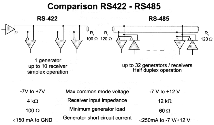
EIA STANDARD RS 422 & RS 485There are two standards describing Balanced interface circuits: EIA-RS 422 (international standard ITU-T V.11) defines point-to-point interfaces with up to 10 receivers for a single transmitter. The limiting parameter is the receiver input impedance Ri=4kOhm. 10 receivers + termination resistor 100 Ohm give the maximum transmitter load. EIA-RS 485 (ISO 8482) defines the input impedance of RS 485 circuits Ri = 12kOhm. Then, up to 32 transmitters, receivers, or combination, can be connected to a single line. Since the data transfer is bidirectional, the line needs to have a terminating resistor at both ends.
Ground potential difference between different devices is +- 7V max, according to EIA-RS 422. EIA-RS 485 defines maximum voltage range at the receiver input (ground potential difference + alternating signal voltage) from -7V to +12V. RS 422/482 circuits have a short-circuit protection. Point-to-point (EIA-RS 422) defines short circuit as a current greater than 150mA, between A and B or against the ground. Multipoint (EIA-RS 485) defines short circuit as current greater than 150mA against the ground, or more than 250 mA between A and B.
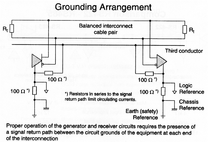
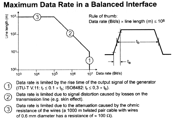
Ground connection for RS 422/485For correct operation of the transmitter and the receiver, a return signal path between the grounding of individual devices is required. It may be realised either by a third wire, or by grounding each device (third pole in the mains socket). If a third (ground) wire is used, resistors (approx. 1kOhm) should be connected in series to eliminate unwanted currents resulting from ground potential differences. Chapter 3: Terminations, capacities, cable lengths, data transfer speedRS 422/485 line termination is essential, especially for faster data transfer rates and long cables. Main reasons for correct termination are reflections at the ends of the line, and the minimum transmitter load requirement. For RS 422, the termination is fairly simple (see picture comparing RS 422 and RS 485). A terminating resistor of 100Ohm is connected to the end of the line. If there are more RS 422 receivers connected to the line, the resistor can be a little bigger. The value can be calculated since the input impedance of the receivers is known. For RS 485, the termination is somewhat more complex (again, see the comparison picture). Since each device communicates bidirectionally (single TP version), we are unable to determine where is the transmitter and where is the receiver - this changes constantly, according to which device transmits at the moment. So, both ends of the line have to be terminated with a 100Ohm terminator. However, it is not that easy. Since all device have tri-state outputs, situations occur (very often - every time the transmitting device or data direction changes), when all transmitters are in high impedance state, and the line, due to termination resistors, is in undefined state (Vab%lt;200mV). It is, however, desirable to define idle state in this situation (Vab<-200mV). Maximum data transfer speeds
This table is for orientation only, but still very useful:
Chapter 4: Protocols, softwareThis chapter is short because software is custom-designed for each individual application, including the transfer protocols. RS 422, as a point-to-point connection, operates similarly to the RS 232 serial port. However, there are certain things software needs to take into account. First, the communication media (TP line) needs to be assigned to individual stations, so that there are no collisions and that responses are fast enough. We have to be aware of the fact, that only a single channel is available for communication. It has to transfer both data and the bit and byte synchronisation. For transferring of individual bits, one of the data network modulations can be used, e.g. coding NRZ, NRZI, phase modulation NRZ, or differential phase modulation. These modulations are not covered in this article, they are a topic of network and protocol theory. For byte synchronisation, several options are available. Maybe the simplest is to reserve one byte to be a sync character. Software then needs to convert data bytes equal to the sync byte to a sequence of different bytes. Or, protocols SLDC/HLDC, suitable for high-speed transfers, may be used. When an application requires only slower data transfer rates (115200bd, or up to 2Mb/s with special UART circuits), we can take advantage of the RS 232 format for both bit and byte synchronisation. This solution saves a lot of effort, especially when a PC is used as Master, and Slave is equipped with a microcontroller containing its own UART, e.g. 8051 compatibles. From a network point of view, the RS 485 incorporates a bus topology. Since Slave stations have no means of starting the communication without a risk of collision, they need to be assigned a 'right to transmit' by the Master station. Assignment is done centrally via pooling, where the central (Master) station periodically asks all Slaves whether they have data to transmit. If so, the questioned station sends the data immediately; otherwise, it replies with a confirmation packet only, or does not reply at all. This method is good for Multipoint systems with smaller number of Slave stations (approx. up to 100). For more stations, the reply would become too slow. Of course, individual system requirements need to be considered. Mentioned 100 stations is for an "on-line" system, where stations have to interactively react to user requests, thus the reply delay needs to be less than 0.5 sec (considered for 115200bd data transfer rate, which is seldom available in industrial environments). Of course, in systems where the Master has no priority function, or due to other factors (e.g. large number of stations with low frequency of data transfers), different access methods may be used. For example, the random access method ALOHA. Here, any station sends its data regardless of the transfer channel status. If a collision occurs, the station does not receive a confirmation, and repeats transmission. However, this method utilises on average only about 18% of available bandwidth, and with larger volumes of data the throughput decreases rapidly due to larger number of collisions. With RS 485, where transmitters can at the same time "listen" for the channel status, the ALOHA method can be improved by a "carrier" (data activity) detection. In this case, stations begin transmission only if the channel is idle. Both methods essentially require a transfer protocol with error detection. In any data transfer, including the RS 485, there is no way to 100% guarantee that a transmitted packet has been successfully received. Especially with the ALOHA methods, collisions may occur; interference, cable length, etc. causes errors too. It is advisable for the communication software to take such situations into consideration. In the central assignment method it is useful for slave stations to send a reply packet with information of last packet received. Several options are available, choice depends on individual use. Chapter 5: More than 32 nodes, handy tips, recommended partsIn case an application requires more than 32 devices, there are basically two options. The simpler is to use transmitters with 4 times the input impedance (48k), allowing to connect up to 128 devices at the same time; these are commonly available nowadays. In this case, we have to adapt the whole termination system. The other option is to use a RS 485 repeater. Such a device has two TP ports. When data appear on one of them, the repeater sends them to the other port, and vice versa. In this way, we can connect another 31 (or 127) stations. Data activity detection can be very simple, using the RS 485 definition - Vab>200mV; or, such a repeater may incorporate its own processor and work as a router as well - like in computer networks. One of the last things I'll mention are commonly available parts for RS 422/485. I have had personal experience with circuits made by MAXIM; they make about ten versions - differences are in speed (0.25 or 2.5 Mbit/s), operation type (half/full duplex), number of devices (32, 128), and in several other parameters. They are labeled MAX481, 485, 487, 491 and so on. Another manufacturer is National Semiconductors, label DS3695A. I assume that every major manufacturer offers some circuits for RS 422/485; however, I don't know any details. Some info in this article comes from excellent publication by Texas Instruments, who make a whole family of RS 422/485 circuits labelled SN 7517X, where X is one- or two-digit type specification. Several hints:
Final wordsThe decision of suitability or unsuitability of RS 422/485 for your application is up to you. I hope that this article has provided you with enough basic info. If you are interested in further details, I recommend especially [1], as well as datasheets by MAXIM. If you are in the process of deciding which type of communication to use in your project, then I hope that this article has brought an inspiration and perhaps saved a lot of time and effort. Of course, if you are interested, you can contact me via e-mail. Literature:
Texas Instruments - Data Transmission design Seminar 97 (SLLDE01B) TP TwistedPair - Two identical wires wrapped around each other. |
Related articles
|
|
May not be used for commercial purposes without prior written permission. All trademarks are properties of their respective owners. Contact: english@hw.cz Powered by  on a Linux/Apache server.
|
 In a RS 232 unbalanced data transmission system, each signal is represented by a voltage level with respect to ground. For example, the TxD signal of a PC COMx port is negative when idle, and switches between positive and negative level when transmitting data. Amplitude ranges between -15 to -5V in negative state, and between +5 to +15V in positive state.
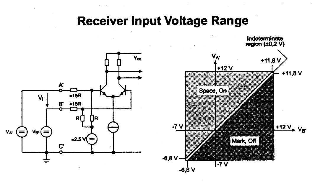 Picture shows a simplified schematics of receiver input connections for a twisted pair line, and a graph of level determination.